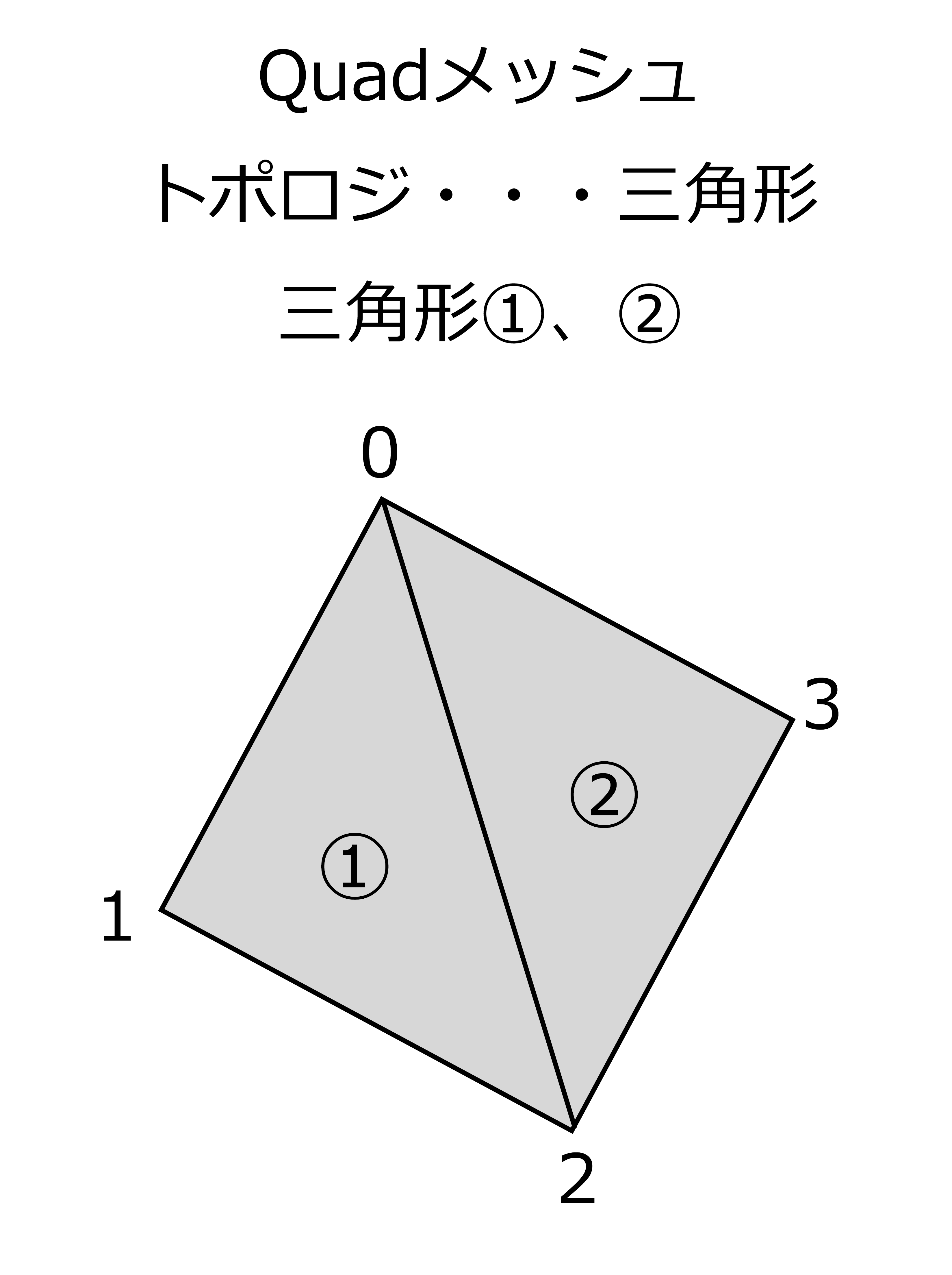
Figure 6.1: Quad mesh
This chapter mainly describes Geometry Shader, which is one of the stages of the rendering pipeline, and explains the dynamic grass-generating shader (commonly known as Grass Shader) using Geometry Shader.
I've used some technical terms to describe the Geometry Shader, but if you're just trying to use the Geometry Shader, it's a good idea to take a look at the sample code.
The Unity project in this chapter has been uploaded to the following Github repository.
https://github.com/IndieVisualLab/UnityGraphicsProgramming/
Geometry Shader is one of the programmable shaders that can dynamically convert, generate, and delete primitives (basic shapes that make up a mesh) on the GPU.
Until now, if you try to change the mesh shape dynamically, such as by converting primitives, you need to take measures such as processing on the CPU or giving meta information to the vertices in advance and converting with Vertex Shader. did. However, Vertex Shader cannot acquire information about adjacent vertices, and there are strong restrictions such as not being able to create new vertices based on the vertices being processed and vice versa. .. However, processing with a CPU would take an unrealistically huge amount of time from the perspective of real-time processing. As you can see, there have been some problems with changing the shape of the mesh in real time.
Therefore, Geometry Shader is installed as standard in DirectX 10 and OpenGL 3.2 as a function to solve these problems and enable free conversion processing within weak constraints. In OpenGL, it is also called Primitive Shader.
It is located on the rendering pipeline after Vertex Shader and before Fragment Shader and rasterization. In other words, within the Fragment Shader, the vertices dynamically generated by the Geometry Shader and the original vertices passed to the Vertex Shader are processed without distinction.
Normally, the input information to Vertex Shader is in units of vertices, and conversion processing is performed for those vertices. However, the input information to the Geometry Shader is a user-defined input primitive unit.
The actual program will be described later, but the vertex information group processed by Vertex Shader will be divided and input based on the input primitive type. For example, if the input primitive type is triangle, three vertex information will be passed, if line, two vertex information will be passed, and if point, one vertex information will be passed. This makes it possible to perform processing while referring to other vertex information, which was not possible with vertex shader, and enables a wide range of calculations.
One thing to note is that Vertex Shader processes on a vertex-by-vertex basis and passes information about the vertices it processes, but Geometry Shader is a primitive assembly topology regardless of the input primitive type. Processing is performed in units of primitives determined by. In other words, if you run the Geometry Shader on a Quad mesh with a topology of Triangles, as shown in Figure 6.1, the Geometry Shader will be run twice for triangles ① and ②. At this time, when the primitive type for input is Line, the information passed to the input is the vertices of two vertices 0,1,2 in the case of triangle ①, and the vertices 0,2,3 in the case of ②. It will be the apex of the two points.
Figure 6.1: Quad mesh
The output of Geometry Shader is a set of vertex information for user-defined output primitive types. In Vertex Shader, it was 1 input and 1 output, but Geometry Shader will output multiple information, and there is no problem even if there is one or more primitives generated by the output information.
For example, if the output primitive type is defined as triangle and a total of 9 vertices newly calculated are output, 3 triangles are generated by Geometry Shader. Since this process is performed in primitive units as described above, it is possible that the number of triangles that were originally one has increased to three.
In addition, it is necessary to set in advance the maximum number of vertices to be output in one process called MaxVertexCount in Geometry Shader. For example, if MaxVertexCount is set to 9, Geometry Shader will be able to output the number of vertices from 0 to 9 points. Due to the "Geometry Shader Limits" described later, 1024 is generally the maximum value for this value.
In addition, as a point to be careful when outputting vertex information, when adding a new vertex while maintaining the original mesh shape, the vertex information sent from Vertex Shader is also sent to Geometry Shader. Must be output. The Geometry Shader does not have the behavior of adding to the output of the Vertex Shader, but the output of the Geometry Shader is rasterized and passed to the Fragment Shader. Paradoxically, you can also dynamically reduce the number of vertices by setting the output of the Geometry Shader to 0.
The Geometry Shader has a maximum number of output vertices and a maximum number of output elements for one output. The maximum number of output vertices is literally the limit value of the number of vertices, and although it depends on the GPU, 1024 is common, so you can increase the number of vertices from one triangle to a maximum of 1024 points. The elements in the maximum number of output elements are the information that the vertices have, such as coordinates and colors. Generally, the position elements of (x, y, z, w) and (r, g, b, a) There are a total of 8 color elements. The maximum number of outputs of this element also depends on the GPU, but since 1024 is also common, the output will be limited to 128 (1024/8) at the maximum.
Since both of these restrictions must be met, even if the number of vertices can be output at 1024 points, the actual output of the Geometry Shader is limited to 128 points due to restrictions on the number of elements. So, for example, if you use Geometry Shader for a mesh with 2 primitives (Quad mesh, etc.), you can handle only up to 256 vertices (128 points * 2 primitives). ..
This number of 128 points is the limit value of the value that can be set in MaxVertexCount in the previous section.
Below is a Geometry Shader program with simple behavior. I will explain the explanation up to the previous section again by comparing it with the actual program.
In addition to Geometry Shader, the explanation about ShaderLab syntax etc. required when writing shaders in Unity is omitted in this chapter, so if you have any questions, please refer to the official document below.
https://docs.unity3d.com/ja/current/Manual/SL-Reference.html
Shader "Custom/SimpleGeometryShader"
{
    Properties
    {
        _Height("Height", float) = 5.0
        _TopColor("Top Color", Color) = (0.0, 0.0, 1.0, 1.0)
        _BottomColor("Bottom Color", Color) = (1.0, 0.0, 0.0, 1.0)
    }
    SubShader
    {
        Tags { "RenderType" = "Opaque"}
        LOD 100

        Cull Off
        Lighting Off

        Pass
        {
            CGPROGRAM
            #pragma target 5.0
            #pragma vertex vert
            #pragma geometry geom
            #pragma fragment frag
            #include "UnityCG.cginc"

            uniform float _Height;
            uniform float4 _TopColor, _BottomColor;

            struct v2g
            {
                float4 pos : SV_POSITION;
            };

            struct g2f
            {
                float4 pos : SV_POSITION;
                float4 col : COLOR;
            };

            v2g vert(appdata_full v)
            {
                v2g o;
                o.pos = v.vertex;

                return o;
            }

            [maxvertexcount(12)]
            void geom(triangle v2g input[3],
                      inout TriangleStream<g2f> outStream)
            {
                float4 p0 = input[0].pos;
                float4 p1 = input[1].pos;
                float4 p2 = input[2].pos;

                float4 c = float4(0.0f, 0.0f, -_Height, 1.0f)
                            + (p0 + p1 + p2) * 0.33333f;

                g2f out0;
                out0.pos = UnityObjectToClipPos(p0);
                out0.col = _BottomColor;

                g2f out1;
                out1.pos = UnityObjectToClipPos(p1);
                out1.col = _BottomColor;

                g2f out2;
                out2.pos = UnityObjectToClipPos(p2);
                out2.col = _BottomColor;

                g2f o;
                o.pos = UnityObjectToClipPos (c);
                o.col = _TopColor;

                // bottom
                outStream.Append(out0);
                outStream.Append(out1);
                outStream.Append(out2);
                outStream.RestartStrip();

                // sides
                outStream.Append(out0);
                outStream.Append(out1);
                outStream.Append(o);
                outStream.RestartStrip();

                outStream.Append(out1);
                outStream.Append(out2);
                outStream.Append(o);
                outStream.RestartStrip();

                outStream.Append(out2);
                outStream.Append(out0);
                outStream.Append(o);
                outStream.RestartStrip();
            }

            float4 frag(g2f i) : COLOR
            {
                return i.col;
            }
            ENDCG
        }
    }
}
In this shader, the center coordinates of the passed triangle are calculated and moved further upward, and each vertex of the passed triangle is connected to the calculated new coordinates. In other words, we are generating a simple triangular pyramid from a flat triangle.
So if you apply this shader to a Quad mesh (consisting of two triangles), it will look like Figures 6.2 through 6.3.
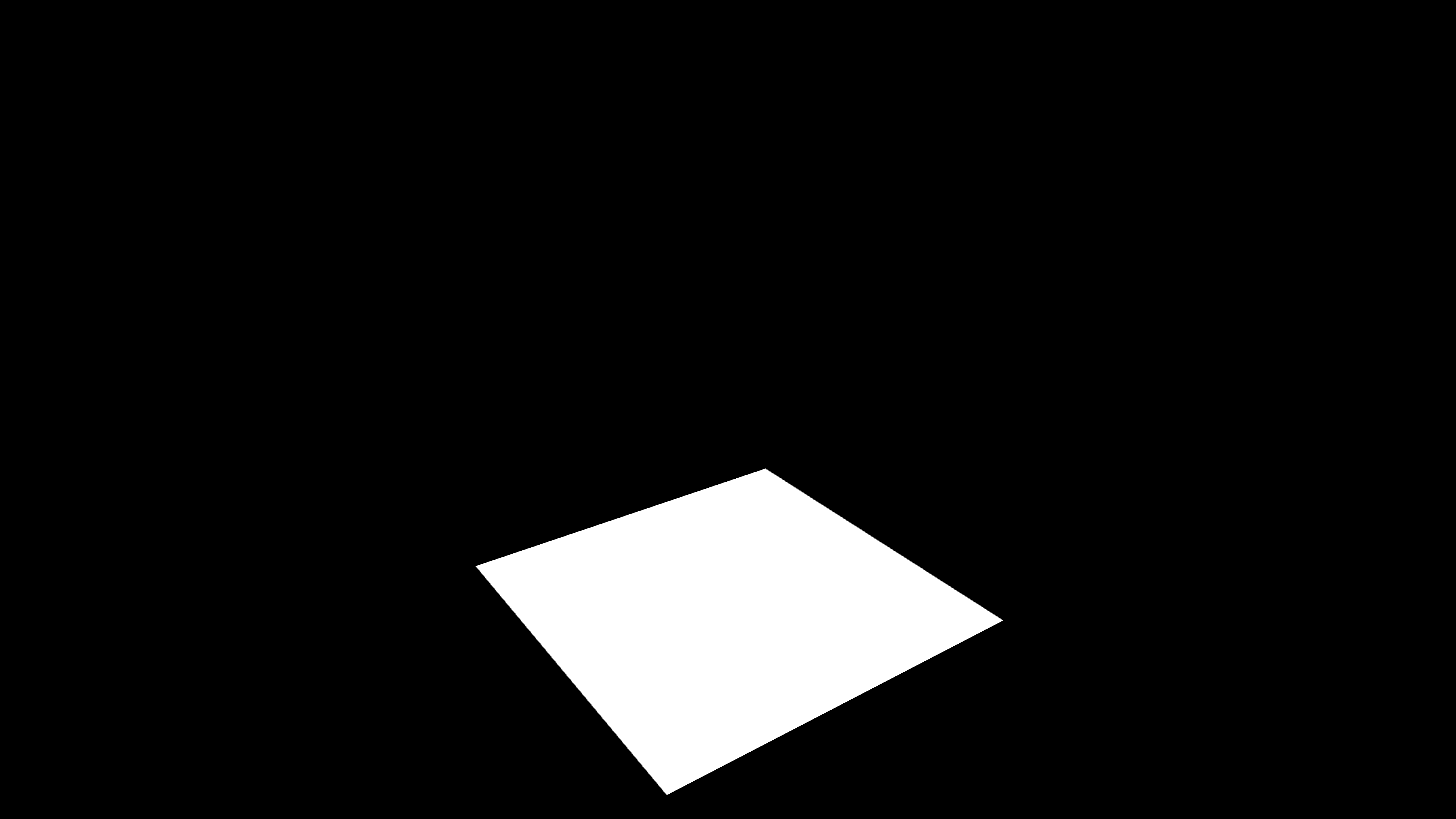
Figure 6.2: From a flat plate like this
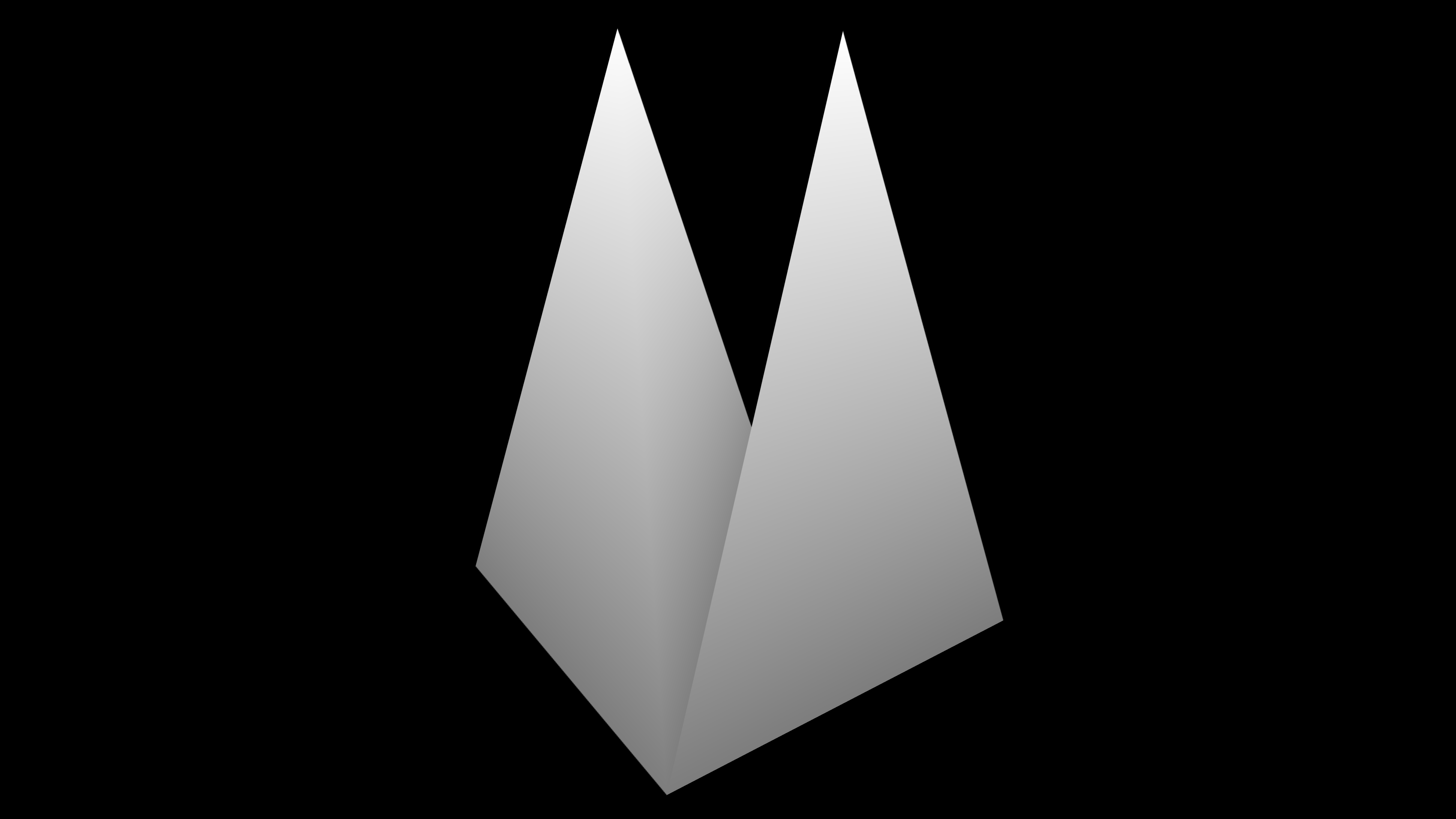
Figure 6.3: Two three-dimensional triangular pyramids are now displayed
In this shader, I will extract and explain only the part related to Geometry Shader in particular.
#pragma target 5.0
#pragma vertex vert

// Declare the use of Geometry Shader
#pragma geometry geom

#pragma fragment frag
#include "UnityCG.cginc"
In the above declaration part, geomwe declare that the function named is a function for Geometry Shader. This geomwill cause the function to be called when the Geometry Shader stage is reached .
[maxvertexcount(12)]
void geom(triangle v2g input[3], inout TriangleStream<g2f> outStream)
Here is the function declaration for the Geometry Shader.
triangle v2f input[3]
This is the part related to input.
This time, I want to generate a triangular pyramid based on the triangle, so I input triangleit. As a result, the information of each vertex of the triangle, which is the unit primitive, is input, and since the triangle is composed of three vertices, the received formal argument is an array of length 3. So, if the input triangleis not input , pointonly one vertex will be composed, so geom(point v2f input[1])it will be received as an array of length 1 like.
inout TriangleStream<g2f> outStream
This is the part related to output.
Since we want to make the primitive of the mesh generated this time a triangle, TriangleStreamwe declare it with a type. TriangleStremaSince the type means that the output is a triangle strip, it will generate a triangle based on each output vertex information. There are other PointStreamtypes and LineStreamtypes, so you need to select the output primitive type according to your purpose.
In addition, [maxvertexcount(12)]the maximum number of outputs is set to 12 in the part. This is because the number of triangles that make up the triangular pyramid is one at the base and three at the side, for a total of four, and three vertices are required for each triangle, so 12 vertices are output with 3 * 4. It is set to 12 because it will be different.
g2f out0;
out0.pos = UnityObjectToClipPos(p0);
out0.col = _BottomColor;

g2f out1;
out1.pos = UnityObjectToClipPos(p1);
out1.col = _BottomColor;

g2f out2;
out2.pos = UnityObjectToClipPos(p2);
out2.col = _BottomColor;

g2f o;
o.pos = UnityObjectToClipPos (c);
o.col = _TopColor;

// bottom
outStream.Append(out0);
outStream.Append(out1);
outStream.Append(out2);
outStream.RestartStrip();

// sides
outStream.Append(out0);
outStream.Append(out1);
outStream.Append(o);
outStream.RestartStrip();

outStream.Append(out1);
outStream.Append(out2);
outStream.Append(o);
outStream.RestartStrip();

outStream.Append(out2);
outStream.Append(out0);
outStream.Append(o);
outStream.RestartStrip();
This is the part of the process that outputs the actual vertices.
First of all, a g2f type variable for output is declared, and vertex coordinates and color information are stored. At this time, it is necessary to convert from the object space to the clip space of the camera in the same way as Vertex Shader.
After that, the vertex information is output while being aware of the order of the vertices that make up the mesh. outStreamOf the variable Appendwill be added to the current stream by passing the output variable to the function, RestartStripto end the current primitive strip by calling the function, you have to start a new stream.
Since this is a TriangleStreamtriangle strip, the more Appendvertices you add in the function, the more connected triangles will be generated based on all the vertices added to the stream. So, Appendif RestartStripyou don't want to be connected based on the order in which the triangles are connected like this time, you need to call once to start a new stream. Of course, it is possible to reduce the number Appendof RestartStripfunction calls by devising the order .
In this section, we will explain Grass Shader, which is a little development from the previous section "Simple Geometry Shader", and uses Geometry Shader to generate grass in real time.
The following is the Grass Shader program described.
Shader "Custom/Grass" {
    Properties
    {
        // Grass height
        _Height("Height", float) = 80
        // Grass width
        _Width("Width", float) = 2.5

        // The height of the bottom of the grass
        _BottomHeight("Bottom Height", float) = 0.3
        // Height of the middle part of the grass
        _MiddleHeight("Middle Height", float) = 0.4
        // Height of the top of the grass
        _TopHeight("Top Height", float) = 0.5

        // The width of the bottom of the grass
        _BottomWidth("Bottom Width", float) = 0.5
        // Width of the middle part of the grass
        _MiddleWidth("Middle Width", float) = 0.4
        // The width of the top of the grass
        _TopWidth("Top Width", float) = 0.2

        // How the bottom of the grass bends
        _BottomBend("Bottom Bend", float) = 1.0
        // How the middle part of the grass bends
        _MiddleBend("Middle Bend", float) = 1.0
        // How the top of the grass bends
        _TopBend("Top Bend", float) = 2.0

        // Wind strength
        _WindPower("Wind Power", float) = 1.0

        // The color of the top of the grass
        _TopColor("Top Color", Color) = (1.0, 1.0, 1.0, 1.0)
        // The color of the bottom of the grass
        _BottomColor("Bottom Color", Color) = (0.0, 0.0, 0.0, 1.0)

        // Noise texture that gives randomness to grass height
        _HeightMap("Height Map", 2D) = "white"
        // Noise texture that gives randomness to the orientation of the grass
        _RotationMap("Rotation Map", 2D) = "black"
        // Noise texture that gives randomness to wind strength
        _WindMap("Wind Map", 2D) = "black"
    }
    SubShader
    {
        Tags{ "RenderType" = "Opaque" }

        LOD 100
        Cull Off

        Pass
        {
            CGPROGRAM
            #pragma target 5.0
            #include "UnityCG.cginc"

            #pragma vertex vert
            #pragma geometry geom
            #pragma fragment frag

            float _Height, _Width;
            float _BottomHeight, _MiddleHeight, _TopHeight;
            float _BottomWidth, _MiddleWidth, _TopWidth;
            float _BottomBend, _MiddleBend, _TopBend;

            float _WindPower;
            float4 _TopColor, _BottomColor;
            sampler2D _HeightMap, _RotationMap, _WindMap;

            struct v2g
            {
                float4 pos : SV_POSITION;
                float3 nor : NORMAL;
                float4 hey: TEXCOORD0;
                float4 rot : TEXCOORD1;
                float4 wind : TEXCOORD2;
            };

            struct g2f
            {
                float4 pos : SV_POSITION;
                float4 color : COLOR;
            };

            v2g vert(appdata_full v)
            {
                v2g o;
                float4 uv = float4(v.texcoord.xy, 0.0f, 0.0f);

                o.pos = v.vertex;
                o.nor = v.normal;
                o.hei = tex2Dlod(_HeightMap, uv);
                o.rot = tex2Dlod(_RotationMap, uv);
                o.wind = tex2Dlod(_WindMap, uv);

                return o;
            }

            [maxvertexcount(7)]
            void geom(triangle v2g i[3], inout TriangleStream<g2f> stream)
            {
                float4 p0 = i[0].pos;
                float4 p1 = i[1].pos;
                float4 p2 = i[2].pos;

                float3 n0 = i[0].nor;
                float3 n1 = i[1].nor;
                float3 n2 = i[2].nor;

                float height = (i [0] .hei.r + i [1] .hei.r + i [2] .hei.r) / 3.0f;
                float rot = (i[0].rot.r + i[1].rot.r + i[2].rot.r) / 3.0f;
                float wind = (i[0].wind.r + i[1].wind.r + i[2].wind.r) / 3.0f;

                float4 center = ((p0 + p1 + p2) / 3.0f);
                float4 normal = float4(((n0 + n1 + n2) / 3.0f).xyz, 1.0f);

                float bottomHeight = height * _Height * _BottomHeight;
                float middleHeight = height * _Height * _MiddleHeight;
                float topHeight = height * _Height * _TopHeight;

                float bottomWidth = _Width * _BottomWidth;
                float middleWidth = _Width * _MiddleWidth;
                float topWidth = _Width * _TopWidth;

                rot = rot - 0.5f;
                float4 dir = float4(normalize((p2 - p0) * rot).xyz, 1.0f);

                g2f o[7];

                // Bottom.
                o[0].pos = center - dir * bottomWidth;
                o[0].color = _BottomColor;

                o[1].pos = center + dir * bottomWidth;
                o[1].color = _BottomColor;

                // Bottom to Middle.
                o[2].pos = center - dir * middleWidth + normal * bottomHeight;
                o[2].color = lerp(_BottomColor, _TopColor, 0.33333f);

                o[3].pos = center + dir * middleWidth + normal * bottomHeight;
                o[3].color = lerp(_BottomColor, _TopColor, 0.33333f);

                // Middle to Top.
                o[4].pos = o[3].pos - dir * topWidth + normal * middleHeight;
                o[4].color = lerp(_BottomColor, _TopColor, 0.66666f);

                o[5].pos = o[3].pos + dir * topWidth + normal * middleHeight;
                o[5].color = lerp(_BottomColor, _TopColor, 0.66666f);

                // Top.
                o[6].pos = o[5].pos + dir * topWidth + normal * topHeight;
                or [6] .color = _TopColor;

                // Bend.
                dir = float4 (1.0f, 0.0f, 0.0f, 1.0f);

                o [2] .pos + =
                            * (_WindPower * wind * _BottomBend)
                            * sin(_Time);
                o [3] .pos + =
                            * (_WindPower * wind * _BottomBend)
                            * sin(_Time);
                o [4] .pos + =
                            * (_WindPower * wind * _MiddleBend)
                            * sin(_Time);
                o [5] .pos + =
                            * (_WindPower * wind * _MiddleBend)
                            * sin(_Time);
                o [6] .pos + =
                            * (_WindPower * wind * _TopBend)
                            * sin(_Time);

                [unroll]
                for (int i = 0; i < 7; i++) {
                    o[i].pos = UnityObjectToClipPos(o[i].pos);
                    stream.Append(o[i]);
                }
            }

            float4 frag(g2f i) : COLOR
            {
                return i.color;
            }
            ENDCG
        }
    }
}
If you apply this shader to a Plane mesh with multiple vertical and horizontal arrangements, it will look like Figure 6.4.
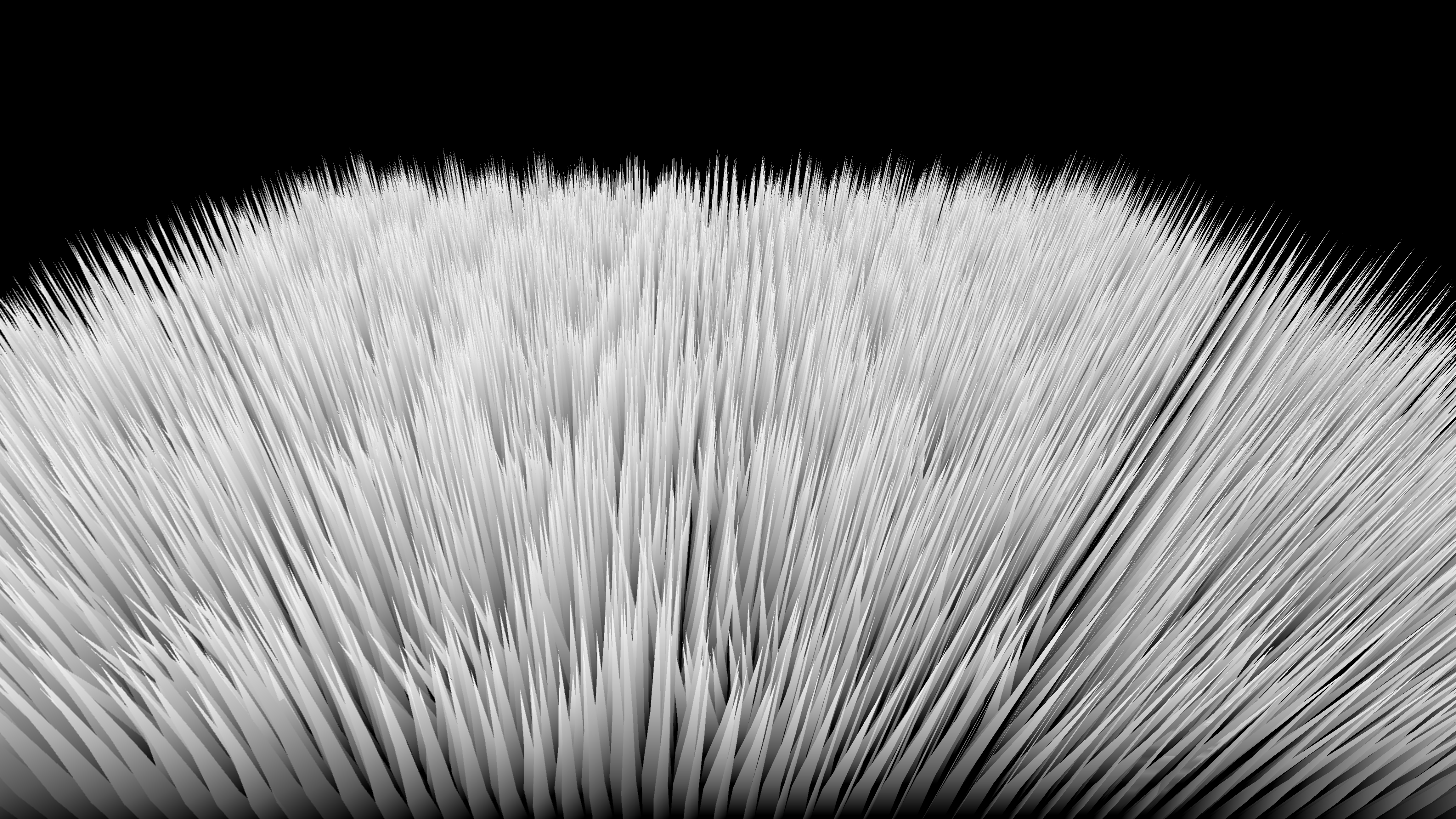
Figure 6.4: Grass Shader results
I will explain the process of growing grass from this.
This time, we will generate one grass for each primitive. As shown in Fig. 6.5, the shape of the grass is divided into the lower part, the middle part, and the upper part, and a total of 7 vertices are generated. I will.
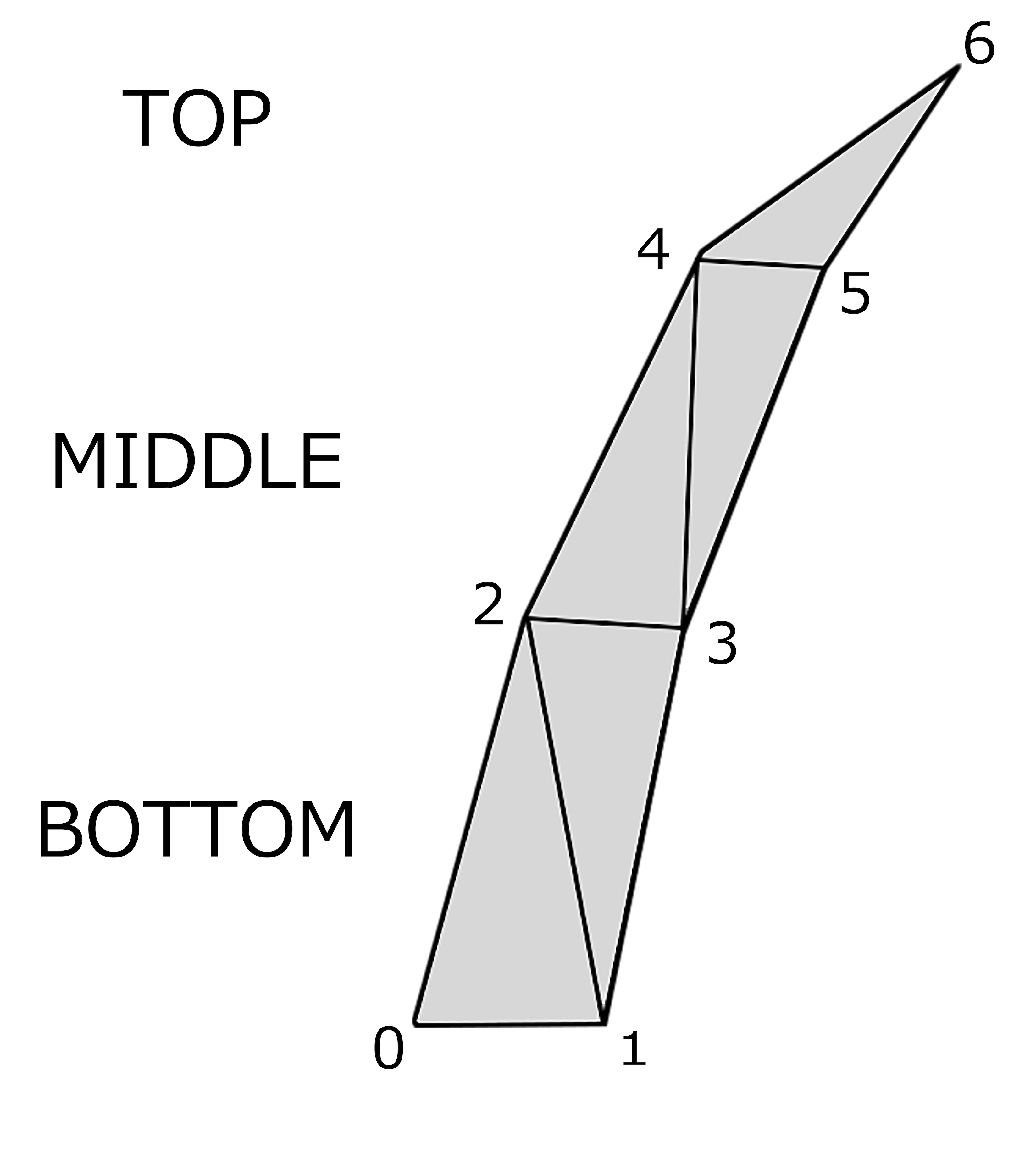
Figure 6.5: How to make a grass shape
Details are described in the comments, but the coefficient that controls the width and height of each part (lower part, middle part, upper part) in one grass, and the coefficient that controls the width and height of the whole grass It is prepared as the main parameter. Also, it doesn't look good if each grass has the same shape, so we use a noise texture to give it randomness.
float height = (i [0] .hei.r + i [1] .hei.r + i [2] .hei.r) / 3.0f;
float rot = (i[0].rot.r + i[1].rot.r + i[2].rot.r) / 3.0f;
float wind = (i[0].wind.r + i[1].wind.r + i[2].wind.r) / 3.0f;

float4 center = ((p0 + p1 + p2) / 3.0f);
float4 normal = float4(((n0 + n1 + n2) / 3.0f).xyz, 1.0f);
In this part, the height and direction of the grass and the numerical values that are the standard of the strength of the wind are calculated. You can calculate in Geometry Shader, but if you give the vertices meta information, you can treat it like the initial value when performing calculation on Geometry Shader, so calculate with Vertex Shader. I am.
float4 center = ((p0 + p1 + p2) / 3.0f);
float4 normal = float4(((n0 + n1 + n2) / 3.0f).xyz, 1.0f);
Here, the central part of the grass and the direction in which the grass grows are calculated. If you decide this part by noise texture etc., you can give randomness in the direction of grass growth.
float bottomHeight = height * _Height * _BottomHeight;

...

o[6].pos += dir * (_WindPower * wind * _TopBend) * sin(_Time);
The program is abbreviated because it is long. In this part, the height and width of the lower part, middle part, and upper part are calculated respectively, and the coordinates are calculated based on that.
[unroll]
for (int i = 0; i < 7; i++) {
    o[i].pos = UnityObjectToClipPos(o[i].pos);
    stream.Append(o[i]);
}
There are 7 vertices calculated in this part Append. This time, there is no problem even if the triangles are generated while being connected, so I have not done so RestartStrip.
In addition, the attribute called is applied to the forstatement [unroll]. This is an attribute that expands the processing in the loop as many times as the number of loops at compile time, and although it has the disadvantage of increasing the memory size, it has the advantage of operating at high speed.
So far, we have explained from the explanation of Geometry Shader to the basic and applied programs. There are some features that are slightly different from writing a program that runs on the CPU, but you should be able to utilize it if you suppress the basic part.
In fact, it is generally said that Geometry Shader is slow. I haven't really felt it, but it may be difficult when the range of use is large. If you are going to use Geometry Shader on a large scale, please take a benchmark etc. once.
Still, being able to dynamically and freely create and delete new meshes on the GPU will greatly expand the range of ideas. Personally, I think the most important thing is not what technology was used, but what is created and expressed by it. We hope that you will learn about and learn about one tool called Geometry Shader in this chapter, and feel some new possibilities.